Category Overview
Gantry welding robots integrate multi-axis overhead bridge structures with automated welding controllers to process large-format, heavy structural components. Unlike articulated arm robots restricted by reach limits, gantry systems utilize dual-side driven overhead rails to expand the longitudinal working envelope without sacrificing torch positioning rigidity. These systems accommodate structural workpieces exceeding 3 meters in width and 12 meters in length, applying continuous MIG/MAG, Submerged Arc Welding (SAW), or TIG processes across heavy plate assemblies.
-
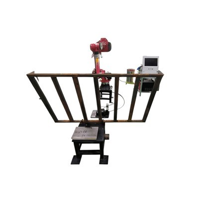
![Gantry Welding Robot For Large Workpieces]() Gantry Welding Robot For Large WorkpiecesThe Chuanglida Intelligent Equipment Gantry Welding Robot is engineered for structural fabrication of oversized components that exceed articulated arm reach. Built on a stress-relieved steel...
Gantry Welding Robot For Large WorkpiecesThe Chuanglida Intelligent Equipment Gantry Welding Robot is engineered for structural fabrication of oversized components that exceed articulated arm reach. Built on a stress-relieved steel... -
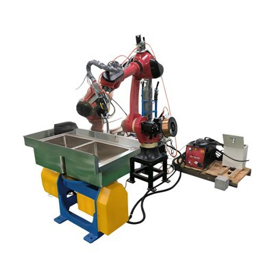
![Gantry Welding Robot For Structural Steel]() Gantry Welding Robot For Structural SteelThe Borun Gantry Welding Robot is engineered for automated joining of heavy structural steel components, including H-beams, box columns, and bridge girders. Built on a rigid dual-side driven...
Gantry Welding Robot For Structural SteelThe Borun Gantry Welding Robot is engineered for automated joining of heavy structural steel components, including H-beams, box columns, and bridge girders. Built on a rigid dual-side driven... -
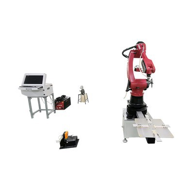
![Long-Span Gantry Welding System]() Long-Span Gantry Welding SystemThe Long-Span Gantry Welding System automates continuous welding for oversized structural components where manual manipulation or standard-reach positioners fail. Built with a rigid structural...
Long-Span Gantry Welding SystemThe Long-Span Gantry Welding System automates continuous welding for oversized structural components where manual manipulation or standard-reach positioners fail. Built with a rigid structural... -
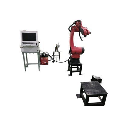
![Large Gantry Welding Robot]() Large Gantry Welding RobotThe Boruntes Large Gantry Welding Robot is an industrial automated platform engineered for structural fabrication of oversized, heavy metal components. Built around a rigid overhead gantry...
Large Gantry Welding RobotThe Boruntes Large Gantry Welding Robot is an industrial automated platform engineered for structural fabrication of oversized, heavy metal components. Built around a rigid overhead gantry... -
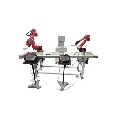
![Dual-Robot Gantry Welding System]() Dual-Robot Gantry Welding SystemThe Borunstech Dual-Robot Gantry Welding System integrates two independent or synchronized 6-axis industrial robots mounted on an overhead structural steel gantry bridge. Designed for workpieces...
Dual-Robot Gantry Welding SystemThe Borunstech Dual-Robot Gantry Welding System integrates two independent or synchronized 6-axis industrial robots mounted on an overhead structural steel gantry bridge. Designed for workpieces... -
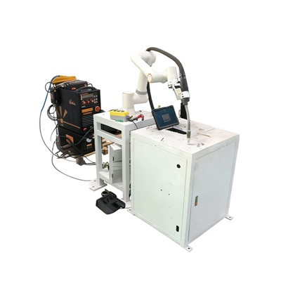
![Single-Robot Gantry Welding System]() Single-Robot Gantry Welding SystemThe Single-Robot Gantry Welding System mounts a 6-axis articulated industrial robot onto an overhead dual-rail bridge structure. Designed to weld long, heavy, or bulky workpieces, this...
Single-Robot Gantry Welding SystemThe Single-Robot Gantry Welding System mounts a 6-axis articulated industrial robot onto an overhead dual-rail bridge structure. Designed to weld long, heavy, or bulky workpieces, this...


Product Range
|
Model Series |
Structure Type |
Longitudinal Travel (X-Axis) |
Transverse Span (Y-Axis) |
Primary Welding Process |
Target Applications |
|
BRG-S Series |
Single-Bridge Gantry |
6,000 - 18,000 mm |
2,000 - 5,000 mm |
MIG/MAG, Flux-Cored Arc |
Box columns, heavy beams, structural frames |
|
BRG-D Series |
Double-Bridge Dual-Carriage |
8,000 - 24,000 mm |
3,000 - 6,000 mm |
Tandem MIG/MAG, Submerged Arc (SAW) |
Ship panels, wind tower sections, large tanks |
|
BRG-C Series |
Cantilever Gantry |
4,000 - 12,000 mm |
1,500 - 3,000 mm |
TIG / Plasma Seam Welding |
Stainless steel pressure vessels, thin-wall cylinders |
Technical Specifications
|
Specification |
Details |
|
Control System |
Multi-axis industrial CNC controller via EtherCAT bus communication |
|
Positional Repeatability |
+/- 0.1 mm (Linear axes) |
|
Maximum Traverse Speed |
15,000 mm/min (X/Y axes) |
|
Z-Axis Vertical Stroke |
Standard 800 mm (Optional up to 1,500 mm) |
|
Drive Mechanism |
AC servo motors with planetary gearboxes and precision ground helical rack-and-pinion assemblies |
|
Guide Rail Specification |
Induction-hardened linear guide rails (Class P5) |
|
Welding Power Source Compatibility |
Digital welding packages from Lincoln Electric, Miller, Fronius, or EWM (350A - 1000A) |
|
Input Power Supply |
3-Phase AC 380V +/- 10%, 50/60Hz |
Rigid Bridge Architecture: Heavy-walled structural steel gantry beams are stress-relieved via high-temperature annealing and precision-machined on a floor-type boring mill to prevent deflection over long spans.
Dual-Side Synchronized Drive: X-axis utilizes dual servo motors and gearboxes linked through electronic gear-ratio synchronization on floor-mounted rack tracks to eliminate mechanical skewing.
Anti-Backlash Transmission
Helical rack-and-pinion assemblies paired with preload gearboxes eliminate dead zone backlash for consistent torch vector control during directional reversals.
Integrated Seam Tracking
Real-time laser triangulation or arc-sensing sensors compensate for thermal distortion and workpiece fit-up variations during multi-pass runs.
Tooling Protection
Vertical Z-axis columns incorporate pneumatic or motorized slide units equipped with crash-protection breakaway mechanisms.
Applications
Structural Steel
Fabrication of heavy H-beams, built-up box columns, crane girders, and bridge structural members.
Energy & Power
Longitudinal and circumferential seam welding for wind turbine tower cans, transformer corrugated walls, and pressure vessels.
Shipbuilding
Panel assembly lines, bulkhead stiffener welding, and large hull section fabrication.
Heavy Transport
Chassis frames for mining trucks, railway freight car bodies, and earthmoving machinery booms.

Seam Tracking Systems: Laser displacement sensors for automatic real-time correction of joint deviations along Y and Z axes.
Wire Feed Management: Barrel-pack wire feeders with dual-wire push-pull mechanisms and automated contact tip cleaning/anti-spatter spraying stations.
Flux Recovery Units: Pneumatic separation cyclones and heating hoppers configured for Submerged Arc Welding (SAW) setups.
Manipulation Interfaces: Synchronized digital I/O handshaking for motorized turning rolls, positioners, or hydraulic clamping fixtures.
Fume Extraction: Local exhaust ventilation ducts mounted directly to the gantry carriage.
Customization
Envelope Expansion
Customized rail lengths and bridge spans engineered to match specific factory floor dimensions and maximum workpiece sizes.
Multi-Torch Configurations
Multi-wire SAW setups or dual-station configurations sharing a single gantry bridge.
Software Integration
Post-processors tailored for offline programming software (Robotmaster / Hypertherm) or custom HMI interfaces integrated into existing MES plant networks.
Environmental Hardening
Thermal shielding and sealed cabling conduits for high-temperature or heavy dust environments.
Manufacturing, Quality Control & Factory Acceptance Testing
ISO 9001 Quality Framework
All manufacturing processes, material traceability protocols, and assembly procedures comply with ISO 9001 quality management standards.
Thermal Stress Relief
Gantry bridge frames and column weldments undergo thermal annealing in a gas-fired furnace at 600°C to 650°C for 6 hours followed by controlled cooling.
Precision Machining
Guide rail mounting surfaces on gantry beams and floor tracks are milled and ground in a single setup on a CNC gantry milling machine to ensure straightness parallelism within 0.05 mm/m.
Laser Interferometer Calibration
Assembled systems undergo dynamic laser interferometer calibration to verify axis positioning accuracy, straightness, and pitch/yaw errors.
Standards & Safety
Electrical Compliance
Control cabinets built to IEC 60204-1 (Safety of machinery - Electrical equipment of machines) utilizing CE-certified components (Schneider, Siemens).
Structural Integrity
Structural calculations comply with AWS D1.1 (Structural Welding Code) and ISO 13920 (Welding - General tolerances for welded constructions).
Safety Interlocks
Emergency stop mushroom buttons on both gantry sides, perimeter light curtains, optical safety scanners, and physical over-travel limit switches on all axes.
Product Selection Guide
Define Workpiece Dimensions: Determine maximum length, width, and weight to establish required X-axis rail length and Y-axis bridge clearance.
Select Welding Process: Choose MIG/MAG for high-speed structural fillets, Submerged Arc (SAW) for deep-penetration thick plate butt joints, or TIG for stainless steel vessels.
Evaluate Joint Complexity: Select standard CNC path control for repetitive straight-line bevels, or add laser seam tracking if thermal distortion or fit-up gaps vary across batches.
Determine Duty Cycle & Station Layout: Assess single-station load/unload times versus dual-station shuttle setups to match throughput targets.
FAQ
As one of the most professional gantry welding robots manufacturers and suppliers in China, we also support customized service. Please feel free to buy discount gantry welding robots in stock here from our factory. For price consultation, contact us.