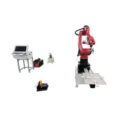
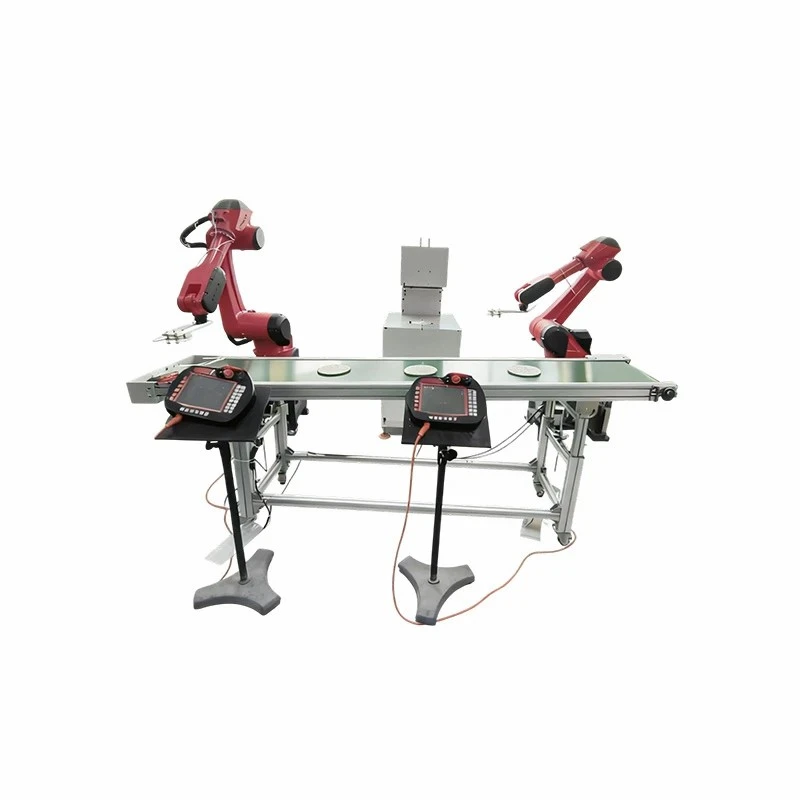
The Overhead Rail Welding Robot mounts a six-axis industrial manipulator onto an elevated gantry or monorail track system. This configuration removes ground-level tracks from the shop floor, prevents obstruction of crane paths, and extends the longitudinal welding envelope beyond 30 meters for oversized workpieces. The structural gantry uses heavy-wall extruded steel rail profiles and precision rack-and-pinion drives to maintain dynamic rigidity during continuous multi-pass welding operations on heavy structural steel and large pressure vessels.
Key Features
Overhead Gantry Suspension: Elevates the robot arm above the workspace, clearing the floor for material handling equipment, heavy staging fixtures, and floor cranes.
Modular Rail Extrusions: Precision-machined, stress-relieved steel rail segments bolt together to extend travel length incrementally without cumulative alignment error.
Backlash-Reducing Planetary Gearboxes: Fitted directly to the rail travel axis to suppress micro-vibrations and maintain smooth torch movement during high-speed MIG/MAG welding.
Real-Time Seam Tracking Integration: Interfaces with laser vision sensors and through-the-arc tracking modules to compensate for thermal distortion and joint fit-up variations on long seams.
Technical Specifications
|
Technical Parameter |
Specification Value |
|
Rail Length (Travel Axis) |
Standard: 6m to 30m (Customizable up to 50m+) |
|
Payload Capacity |
120 kg to 210 kg (Robot arm dependent) |
|
Positional Repeatability |
+/- 0.05 mm (Robot arm) / +/- 0.15 mm (Rail gantry axis) |
|
Maximum Travel Speed |
1.5 m/s (Rail translation axis) |
|
Compatible Welding Processes |
GMAW (MIG/MAG), FCAW, SAW, Laser-MIG Hybrid |
|
Welding Power Source |
350A - 500A digital inverter |
|
Operating Voltage |
380V / 415V / 480V, 3-Phase, 50/60 Hz |
|
Ambient Operating Temperature |
0°C to 45°C |
Applications
Construction Machinery
Longitudinal box beams, excavator booms, and crane structural frames.
Shipbuilding
Flat panel assembly, deck stiffeners, and large hull section sub-assemblies.
Energy Equipment
Wind turbine tower sections, pressure vessels, and transformer tanks.
Railway Transportation
Locomotive underframes, bogie frames, and structural freight car bodies.
Welding System
Power Source Integration: Communicates with digital synergic pulse welding machines via EtherCAT or Profinet protocols to control droplet transfer and minimize spatter.
Wire Feed Mechanism: Push-pull wire feeding configuration mounted directly above the torch assembly to eliminate bird-nesting and ensure stable wire delivery over extended reach configurations.
Torch Collision Sensor: Pneumatic or magnetic breakaway sensor mounted between the wrist and torch to halt operations instantly upon physical obstruction, preventing structural damage to the torch assembly.
Automatic Torch Cleaning Station: Programmable pneumatic reamer station with anti-spatter fluid spray injection integrated directly along the rail servicing zone.
Customization Options
Axis Configuration: Configurable as a single robot on a linear rail, dual synchronized robots on a shared rail, or multi-axis gantry bridges with transverse cross-slides.
Fume Extraction Integration: On-torch suction channels or moving gantry-mounted local exhaust ventilation hoods linked to central filtration units.
Workpiece Synchronization: Coordinated motion control linking the overhead rail axis with external workpiece positioners (turn-tables, headstock-tailstock rotators).
Environmental Protection Packages: Heat shields, pressurized cabinet optics, and bellows covers for high-temperature or heavy-slag operating environments.
Integration Architecture & Control Ecosystem
Master Controller Hierarchy: Industrial robot controller paired with a dedicated gantry motion PLC linked via high-speed deterministic fieldbus (Profinet / EtherCAT) for real-time kinematic synchronization.
External Axis Synchronization: Seamless multi-axis coordination allowing the robot torch to interpolate simultaneously with headstock-tailstock rotators or motorized positioners during continuous welding.
Industry 4.0 / MES Data Logging: Ethernet-based data export interface capturing arc-on time, wire consumption, welding current/voltage logs, and error codes for quality traceability and predictive maintenance analytics.
Safety Systems & Compliance Architecture
Perimeter Safety Interlocking: Hard-wired safety PLC integration supporting light curtains, safety area scanners, and emergency stop muting zones along the rail travel path.
Mechanical Hard Stops: Heavy-duty physical bumper blocks with energy-absorbing shock absorbers installed at both ends of the rail stroke to prevent over-travel derailment.
Arc Flash & Fume Containment: Interlocked safety welding curtains, automated pneumatic shutter shields, and localized exhaust pickup points designed to meet regional occupational health and safety standards.
Manufacturing & Quality Control
Base Structure Machining: Gantry base plates and rail mounting surfaces milled on large-scale CNC gantry milling centers to achieve flatness tolerances within 0.03 mm per meter.
Thermal Stress Relief: All structural weldments undergo thermal annealing prior to precision machining to eliminate residual stresses and prevent long-term structural deformation.
Geometric Laser Calibration: Rail straightness, parallelism, and orthogonality measured using laser interferometer tracking systems during factory assembly.
Load and Burn-in Testing: Systems undergo a 72-hour continuous dry-run endurance test and a simulated load test matching rated payload before crating.
Compliance Standards: Built in accordance with ISO 12100 (Safety of Machinery) and IEC 60204-1 (Electrical Equipment of Machinery).
Commissioning, Site Acceptance (FAT/SAT) & Training
Factory Acceptance Testing (FAT): Pre-shipment verification protocols conducted at the manufacturing facility, including geometric laser tracking, 72-hour dry-run endurance tests, and optional customer-witnessed sample welding trials.
Site Acceptance Testing (SAT): On-site calibration, path accuracy verification, and dry-run testing executed by field engineers once the gantry is anchored to the foundation.
Operator & Maintenance Training: Structured multi-day on-site training covering robot pendant programming, multi-pass parameter tuning, routine mechanical upkeep, and error recovery protocols for shop-floor personnel.
Lifecycle Support & Maintenance Assurance
Remote Diagnostics Module: Secure VPN router integrated into the control cabinet for real-time PLC/robot program troubleshooting and software updates by application engineers.
Preventive Maintenance Schedule: Centralized auto-lubrication system delivers metered grease to rail guide blocks and rack teeth at programmable intervals.
Spare Parts Availability: Critical components-including servo drives, teach pendants, proximity sensors, and contact tips-stocked in regional distribution hubs with guaranteed dispatch within 48 hours.
Engineering Documentation: Delivery includes comprehensive mechanical assembly drawings, electrical schematics (EPlan format), PLC address lists, and kinematic calibration certificates.
FAQ
Q: How is structural deflection managed over a 20-meter rail span?
A: The gantry structure utilizes finite element analysis (FEA) optimized box-section bridge beams and oversized linear guide rails. Adjustable leveling shims and anchor bolt arrays secure the foundation plates to a reinforced concrete slab, keeping structural deflection under full load below 0.2 mm per meter.
Q: Can the overhead rail system integrate with existing welding power sources?
A: Yes. The robot controller supports standard industrial fieldbus interfaces (DeviceNet, Profibus, Profinet, Ethernet/IP) to communicate with third-party digital welding machines, provided the power source features an external analog or digital control interface.
Q: What is required for site preparation prior to installation?
A: Site preparation requires a reinforced concrete foundation (minimum 250 mm thickness), overhead clearance verified against factory crane paths, and dedicated 3-phase electrical drops with appropriate circuit breaker protection near the installation zone. Foundation anchor layout drawings are provided during the engineering sign-off phase.
Q: How does the system handle power and signal transmission over long travel distances?
A: Power and control signals are routed via a continuous, heavy-duty enclosed cable carrier track (energy chain) rated for millions of flexing cycles, preventing cable fatigue or entanglement during high-frequency gantry translation.
Hot Tags: overhead rail welding robot, China overhead rail welding robot manufacturers, suppliers, factory, automated welding fixture handling system, automated welding production system robot, cobot welding robot, Custom Robotic Arc Welding Workstation, industrial welding automation cell, welding robot transfer workstation system